Introduction
The hours before a foundation pour are the last chance to catch rebar errors — after concrete covers the steel, every fix means breaking concrete. This checklist walks the full pre-pour verification for footing reinforcement: sizes, laps, cover, supports, ties, and inspection. Work through it the evening before the pour, not the morning of. Quantities come from the Foundation Rebar Calculator; the field techniques behind several of these checks are in the pro tips guide.
1. Design and Documentation
- Approved drawings on site. The crew works from the current structural drawings — not from memory, not from an old revision. Confirm the revision date matches the permit set.
- Cut list reconciled. Every piece placed traces to a line on the cut list; every cut-list line is either placed or accounted for as waste/offcut. No orphans, no gaps.
- Delivery tickets match the spec. Bar sizes, grade (Grade 60 vs 40), and coating (black vs epoxy) on the tickets match the drawings. Spot-check rolled-in mill marks on a few sticks.
- Lap schedule confirmed. The design’s required lap lengths are known and marked — not assumed from the 40-diameter planning figure used in the estimate.
2. Bar Sizes, Grades, and Layout
- Correct size in each position. #5 where the design says #5, #4 where it says #4 — mixed-up sizes are invisible after the pour.
- Correct number of bars per section. Count bars in several cross-sections: 3 longitudinal bars means 3, everywhere.
- Bars run the full design length. No short bars “close enough” to the end — bars that stop short of their development length don’t develop full strength.
- Corner bars in place. L-shaped corner ties connect the runs at every corner and T-junction, with proper bend radius and hook allowances.
- Dowels for walls/columns above. Vertical dowels are positioned, correct size and height, and tied — they can’t be added after the pour.
3. Lap Splices
- Every lap meets the design length. Measure laps with a tape — e.g., 25 in (635 mm) minimum for a #5 bar at 40 diameters — at several splices per run.
- Laps are staggered. Adjacent bar lines don’t splice at the same cross-section; splices are offset by at least the lap length.
- Each lap is tied. Minimum two ties per splice — one near each end of the overlap — so bars can’t separate during concrete placement.
- Lap count matches the estimate. Runs longer than one stick have the expected number of joints (sticks − 1 per line); a missing lap means a bar is short somewhere.
4. Spacing and Cover
- Spacing matches the design. Check transverse bar spacing center-to-center at several points — 24 in on center means 24 in, not “about two feet.”
- Cover on all soil-facing sides: 3 in (75 mm) typical. Measure from bar surface to form/soil face at the bottom and both sides. The code compliance guide covers cover requirements.
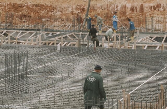
- Supports under all bottom steel. Chairs or concrete dobies every 4–5 ft (1.2–1.5 m) — no bars resting on soil, and no long unsupported spans that sag.
- Top steel supported too. Upper rows sit on chairs or supports spanning from below — steel resting on nothing ends up wherever gravity puts it.
- Side cover maintained. Bars centered in the section with spacers where steel runs close to formwork.
5. Ties and Cage Integrity
- Ties at laps and key intersections. Every third or fourth intersection tied, every lap double-tied — the cage should not rack when pushed.
- No broken or missing ties. Walk the full cage and re-tie any snapped wires.
- Cage is square and aligned. Check diagonals on tied sections; verify the cage sits centered in the forms, not drifted to one side.
- Walkways planned. Planks over the steel so the pour crew doesn’t walk on the cage — foot traffic is the top cause of displaced bars.
6. Cleanliness
- Bars free of mud, oil, and loose rust. Contamination breaks the concrete-steel bond. Wire-brush any muddy or flaky sections; light surface rust (tight mill scale) is acceptable.
- Forms and trench clear of debris. No wood scraps, wire offcuts, or standing water in the excavation — they become voids or bond-breakers.
- Coating intact (if epoxy-coated). Touch up any nicks with repair compound before the pour.
7. Inspection and Pour Readiness
- Steel inspection scheduled and passed. The inspector has seen and approved the reinforcement before concrete placement. Confirm the sign-off is documented.
- Cage photographed. Photos with a tape in frame at laps, cover dimensions, and dowel positions — cheap insurance for any later question.
- Concrete order matches the pour. Mix design, slump, and volume confirmed with the supplier; the pour sequence keeps the cage undisturbed.
- Vibrator plan briefed. Crew knows to consolidate beside the steel, not against it — and someone watches cover during the pour.
- Weather check. Rain, freezing temperatures, or extreme heat each change pour-day procedures — confirm the plan accounts for the forecast.
Quick-Reference: The Five Fatal Checks
If time is short, these five catch the failures that matter most:
- Lap lengths — measured, not eyeballed, at every accessible splice.
- Cover — 3 in (75 mm) from soil faces, verified with a tape at multiple points.
- Supports — no steel touching soil anywhere.
- Dowels — present, correct, and tied for everything built above.
- Inspection sign-off — documented before the truck arrives.
Related Guides
- Pro Tips — ordering, tying, and inspection advice.
- Common Mistakes — the errors this checklist is designed to catch.
- Code Compliance — cover, minimum steel, and lap splice rules.
- Estimating Guide — step-by-step measurement and counting workflow.
- FAQ — quick answers to the most asked questions.
Check It Before You Pour It
A pre-pour walk takes an hour; fixing buried steel takes days. Print this checklist, walk the cage with the Foundation Rebar Calculator cut list in hand, measure the laps and the cover, confirm the inspection sign-off — and then pour with confidence.
Open the Foundation Rebar Calculator
Disclaimer: Calculator results are planning estimates based on the dimensions and layout you enter. Inspection requirements and code provisions vary by jurisdiction — verify with your local building authority. Verify quantities with your supplier, have structural designs reviewed by a qualified engineer, and check your local building code before ordering or installing.